
|
|
 |
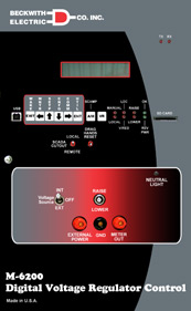
LTC Transformer and Regulator Controls |
 |
Synchronizing (Speed and Voltage Matcher) |
 |
Capacitor Control |
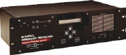
M-3425A Generator Protection System Integrated Protection System® for Generators of All Sizes The Integrated Protection System M-3425A provides protection, control, monitoring and user interface functions for generator protection. Stored targets and oscillography can be IRIG-B synchronized. Dual RS-232 ports and an RS-485 port provide user-interface communication capabilities. The M-3820D IPScom® Communications Software is included for direct serial or remote communication access. Waveform data can bedownloaded using the M-3801D IPSplot® PLUS Oscillograph Analysis Software which allows for plotting and printing of the downloaded oscillographic data.
|
 |
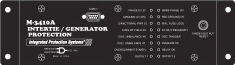
M-3410A Intertie/Generator Protection Relay Facilitates standardization for small/medium intertie and generator protection applications The M-3410A Intertie/Generator Protection Relay is a microprocessor-based unit that uses digital signal processing technology to provide up to twelve protective relaying functions for intertie protection or up to eleven protective relaying functions for generator protection. Generator Protection The relay can protect a generator from abnormal voltage, abnormal frequency, motoring (loss of prime mover), phase faults, ground faults, and unbalanced currents. In addition, sync check may be applied for proper connection of the generator to the bus. Intertie Protection The relay can protect the utility from having generators island on the distribution system after the utility disconnects power from the feeder. This is accomplished by monitoring the intertie (point of common coupling to the utility) for abnormal voltage, abnormal frequency, ferroresonance and excessive power import/export, which can indicate loss of utility supply. The relay also provides detection of phase and ground faults, as well as current and voltage unbalance on the utility system. In addition, sync check may be applied to supervise closure of the intertie breaker according to the interconnected utilitys practice |
|
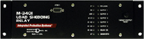
M-3401 Load Shedding Relay Integrated Protection System®
|
|
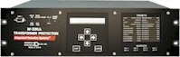
M-3311A Transformer Protection System Two, Three or Four Winding Protection for Transformers of All Sizes The Transformer Protection System M-3311A provides protection, control, monitoring and user interface functions for two, three or four-winding transformers. Includes restrained and unrestrained differential protection, overcurrent protection, and optional voltage, and underfrequency protection. Multiple setpoint groups and user-implementable logic schemes provide flexibility. Dual RS-232 ports and an RS-485 port provide user-interface capabilities. Optional modules include the HMI Module for front-panel operation, the Target Module to indicate trip target status and redundant power supply. The M-3311A can be purchased as a differential and overcurrent relay or with the Optional Voltage Protection Package. The M-3826 IPScom® Communications Software is included for direct serial or remote communication access. Waveform data can be downloaded using IPScom®, while the M-3801D IPSplot® PLUS Oscillographic Analysis Software allows for plotting and printing of the downloaded oscillographic data.
|
|
|
M-3311 Transformer Protection System Three-Winding Protection for Transformers of All Sizes Reduce project and ownership costs
| |
|
M-3310 Transformer Protection System 2-Winding Protection for Transformers of All Sizes
| |
|
M-3410A Intertie/Generator Protection Relay Facilitates standardization for small/medium intertie and generator protection applications The M-3410A Intertie/Generator Protection Relay is a microprocessor-based unit that uses digital signal processing technology to provide up to twelve protective relaying functions for intertie protection or up to eleven protective relaying functions for generator protection. Generator Protection The relay can protect a generator from abnormal voltage, abnormal frequency, motoring (loss of prime mover), phase faults, ground faults, and unbalanced currents. In addition, sync check may be applied for proper connection of the generator to the bus. Intertie Protection The relay can protect the utility from having generators island on the distribution system after the utility disconnects power from the feeder. This is accomplished by monitoring the intertie (point of common coupling to the utility) for abnormal voltage, abnormal frequency, ferroresonance and excessive power import/export, which can indicate loss of utility supply. The relay also provides detection of phase and ground faults, as well as current and voltage unbalance on the utility system. In addition, sync check may be applied to supervise closure of the intertie breaker according to the interconnected utilitys practice |
|
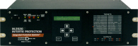
M-3520 Intertie Protection System Integrated Protection System® for Generators of All Sizes The Intertie Protection system M-3520 provides protection, control, monitoring and user interface functions. Includes protection for abnormal voltage and frequency, current unbalance (negative sequence), and directional power. Sync-check, VT fuse loss and directional phase and ground overcurrent protection are also provided. Stored targets and oscillography can be time-stamped. Dual RS-232 and RS-485 communication ports provide user-interface capabilities. The M-3822 IPScom® Communications Software is included for direct serial or remote communication access. Waveform data can be downloaded using IPScom, while the M-3801D IPSplot® Plus Oscillographic Analysis Software allows for plotting and printing of the downloaded oscillographic data.
|
|
|
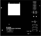
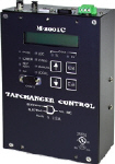
M-2001C Tapchanger Control M-2001C Universal Tapchanger Control enhanced to provide even more benefits to both OEM's and customers alike! Beckwith Electric now offers four M-2001C models to better match user applications while offering price concessions including the Comprehensive, Base-T, Base-RS, and Base-R.
The M-2001C provides a menu-driven software through the HMI that prompts the operator with an easy to understand display. Settings, metering, DNP3.0 data point selection and control configuration is available through the M-2029 TapTalk® software. |
|
|
M-0390 Syncrocloser® Check Plus Relay Secure reclosing of a circuit breaker The M-0390 Syncrocloser® Check Plus Relay is used as a permissive relay for secure reclosing of a circuit breaker by verifying that voltage and phase angle conditions are within pre-set limits before allowing the breaker to close. The M-0390 uses phase angle/slip frequency to verify synchronism to provide rapid restoration with the smallest possible angle settings. It is a panel-mounted, direct upgrade for G.E. IJS and SLJ, and Westinghouse CVE relays.
|
|
M-0188A Syncrocloser® Check Relay The M-0188A Syncrocloser Check Relay is used as a permissive relay for secure reclosing of a circuit breaker by verifying that voltage and phase angle conditions are within pre-set limits before allowing the breaker to close. Adjustable front panel controls are provided for upper and lower voltage limits, voltage difference (ΔV) limit, phase angle limit, time delay and dead line/bus limits. Analog outputs of phase angle, voltage and ΔV are provided for SCADA system interface. Phase angle, voltage and time delay dial settings are independent and do not vary with input conditions.
|
|
|
M-0359 Syncrocloser Check Plus Relay The M-0359 Syncrocloser? Check Plus Relay is used as a permissive relay for secure reclosing of a circuit breaker by verifying that voltage and phase angle conditions are within pre-set limits before allowing the breaker to close. The M-0359 uses phase angle/slip frequency to verify synchronism to provide rapid restoration with the smallest possible angle settings without a time delay. Analog outputs of phase angle, bus voltage, line voltage, ΔV and ΔF are provided for SCADA system interface.
|
|
Capacitor Control |
|
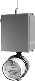
M-2501B Autodaptive® Capacitor Control Pole-Top Distribution Capacitors The M-2501B Autodaptive Capacitor Control (ACC) switches pole-top capacitor banks according to changing system VAr needs, resulting in better distribution line voltage regulation and lower system losses. This action also increases supply equipment capacity to provide more power to distribution customers.
|
|
|
|